In the late 1970s BP Research (the research arm of the oil giant British Petroleum Ltd) and the National Physical Laboratory (NPL) in Teddington teamed up on a project to develop a laser based system for the quantification of pollutant gases in the atmosphere.
The novel technique to be used was given the acronym DIAL, which stood for DIfferential Absorption LIDAR. LIDAR, itself an acronym for LIght Detection And Ranging, was a technique already in use by the military and others to detect the distance of target objects from a gun emplacement or mobile unit. LIDAR works on the same principles as RADAR but uses laser light instead of radio waves or microwaves as the measurement medium. The time taken for the laser light to make the round trip between the LIDAR source and the target object is measured and then multiplied by the speed of light to give the distance between the target and the LIDAR.
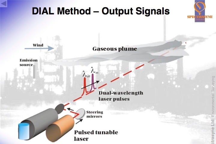
DIAL is a development of LIDAR and uses a pulsed laser source which produces short packets/beams of laser light alternately at two different wavelengths. The wavelengths or “colours” of laser light are chosen to be absorbed by the (λon) and much less, or not absorbed at all by the pollutant gas (λoff), thus giving a differential in the amount of absorption between the two wavelengths. These wavelengths are determined by reference to the unique “fingerprint” or spectral analysis of the target pollutant gas. It is also crucial that only the target gas has a differential absorption at these two wavelengths, so the fingerprints/spectral analyses of all other gases present in the atmosphere have to be checked before the final wavelengths are defined for each target gas.
The laser source used has to be tuneable, so that different pairs of wavelengths can be used for different gases and, of course, the gap between them has to be moveable too. As the laser source is also pulsed i.e. sends out discrete packets of light, each pair of pulses can be used to make a measurement.
The first “more absorbed” pulse (λon) is timed as it leaves the source. As it travels through the atmosphere, every time comes upon a molecule of the target gas a little of it is absorbed by the molecule and every time it comes into contact with a piece of dust or aerosol the light is scattered and a tiny fraction of the scattered light is effectively “reflected” back to the source where a detector is housed. The detector measures the amount of light received and the time it receives it. Some of the light from the pulse proceeds on its journey forward into the atmosphere. These absorption and scattering processes continue along the path taken by the laser beam until there is no light left in the packet/pulse. The data collected by the detector can then be used to determine the amount of target gas in the round trip between itself, the point of scattering and laser source because the size of the absorption the of that specific wavelength of light by each molecule of target gas was predetermined by the spectral analysis.
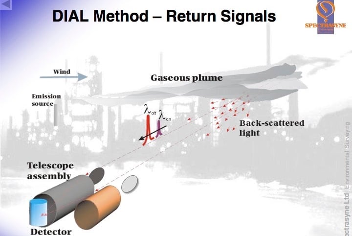
But the amount of light lost to scattering has also to be accounted for, this is achieved by using the data from the second “less absorbed” pulse (λoff). When it is sent out into the atmosphere, it receives the same scattering etc, but little or no absorption by the target gas molecules. So the amount of light received by the detector and the times from this beam can be matched with the first beam and used as the reference measurements.
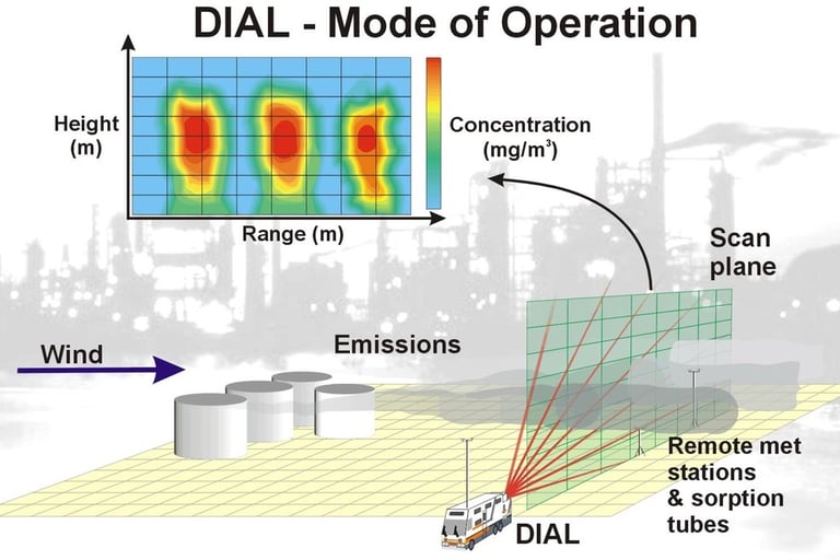
From the normalised intensities collected from the two wavelengths (λon and λoff) at the same “round trip times” the correct number of target gas molecules encountered in the round trip path can be determined. As the timed data collected by the detector also gives the distance at which scattering occurred, a picture can be built up of the number of molecules or the concentration of the target gas between the detector and the various points of scattering.
By looking at the differences between these lines of concentration the change in concentration along the beam path can be calculated. A range resolved concentration profile can be produced. It is important that the two wavelengths (λon and λoff) are kept close spectrally (in colour) and are sent into the atmosphere close temporally so that they will both be scattered by the atmosphere in the same way.
By scanning the laser beams through the target gas cloud or plume a two dimensional picture of the concentration can be produced. If the wind velocity driving the plume through the laser beam path is also measured the mass emission of the target gas can be attained. Simplistically, this calculation is as follows: the concentration is integrated over the cross-sectional area of the plume and multiplied by the wind speed c.f. mg/m3 x m2 x m/s = mg/s.
History and the DIAL Technique
The prototype DIAL system, mounted in a truck, operated in the ultraviolet region of the spectrum and was proved and tested over a period of years at BP sites in the UK. In the ultraviolet spectral region the prototype DIAL was mainly used to measure SO2, but by the mid 1980s it became clear that the fugitive hydrocarbon gases emitted from oil and gas installations were of more concern and could not at that time be measured. Driven by the environmental authorities in Gothenburg in Sweden, who were pressurising the BP Refinery there to measure fugitive hydrocarbons, the project was then directed towards developing suitable infrared laser source for the DIAL. Most non aromatic hydrocarbons have suitable absorptions in the infrared around the 3.3um wavelength range. By 1988 a prototype Infrared DIAL system had been developed and built.
At the beginning of 1989, having field tested and proved the prototype infrared system, the BP Research DIAL Team effort concentrated on the construction, development, and testing of a commercial, BP system which incorporated a number of recent technological improvements in optical and laser equipment and fast data transfer and communications hardware. The philosophy for the commercial system was strongly biased towards operational criteria with emphasis on time efficiency and automation wherever possible. This first ever commercial DIAL system was successfully commissioned on schedule during the third quarter of 1990, and during the fourth quarter it was fully proved and field tested at two BP Oil sites in the UK.
Meantime, in response to the Swedish authorities pressure, the prototype system was deployed at the BP Refinery in Gothenburg 1988 and 89. The results from the first measurement survey were used to make improvements and fix leaks etc that were detected with the DIAL. The outcome was a saving, at that time, of $0.75 million of previously lost hydrocarbon material compared with the 1988 survey figures. The survey results were received well by the authorities and consequently the pressure on the BP Refinery was reduced.
With increasing public and political pressure for environmental protection legislation, in 1992, the BP DIAL team personnel undertook a management buy-out of the commercial DIAL system from BP Research and formed Spectrasyne Ltd. As an independent company the DIAL technology could then be used by all the oil and gas companies to tackle the monitoring problems existing and impending legislation would create.